Yanzhi Testing - Analysis of BC Cell Technology and How Testing Solutions Can Facilitate Its Maturation
BC Battery Definition
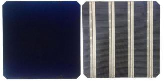
Back Contact (BC) cells are a technology where both the positive and negative metal contacts are placed on the rear side of the cell. This front-side shading-free structure increases the effective light-receiving area of the module, enhancing the conversion efficiency of photovoltaic modules. BC cell technology has garnered significant attention in the photovoltaic industry due to its high efficiency and aesthetically pleasing front-side appearance.
Figure 1. Front and Rear Appearance of IBC Cells
Note: Left image shows the front side, right image shows the rear side.
Compared to traditional cell technologies, the front-side shading-free structure can increase the effective light-receiving area by approximately 4%-5%, potentially boosting conversion efficiency by about 1 percentage point. For example, in a traditional bifacial electrode module with 182mm size and 16BB, assuming a ribbon width of 0.26mm and fine grid width of 25µm, the front-side shading area accounts for about 4.07% of the total cell area. By adopting the front-side grid-free design of BC cells, the effective light-receiving area can be increased by approximately 4.24%. Assuming a traditional bifacial electrode module has a conversion efficiency of 22.50%, the front-side grid-free design could potentially increase its efficiency by 0.95 percentage points, all else being equal. Additionally, this design avoids the trade-off between contact resistance and doping concentration on the light-receiving surface, allowing for reduced doping concentration to minimize recombination, enhance passivation, reduce parasitic absorption in the doped region, and increase open-circuit voltage and short-circuit current. Furthermore, BC cells can optimize the contact width of the electrodes to reduce series resistance, potentially further improving conversion efficiency.
Technical Progress
BC cell technology has transitioned from the early exploration phase to the industrialization stage. Currently, BC technology can be integrated with other photovoltaic cell technologies such as TOPCon and HJT, forming advanced cell technologies like TBC (Tunneling Oxide Passivated Contact Back Contact) and HBC (Heterojunction Back Contact). These technologies combine the high efficiency and front-side shading-free advantages of BC cells with the high passivation quality and low temperature coefficient of other cell technologies, further enhancing cell performance. As shown in Figure 2 below:

Source: "Crystalline Silicon Back Contact Solar Cell Technology and Development" by Shen Wenzhong, PuLe Tech, BOC International
Figure 2. Schematic Diagram of XBC Cell Structure
Differences Among XBC Technologies
The differences mainly lie in substrate materials and passivation methods, requiring a balance between cost and conversion efficiency. The variations among XBC cell structures are primarily reflected in the choice of materials for each layer: Since BC technology is essentially a platform technology, it can be combined with PERC, TOPCon, and HJT technologies to form P-IBC, TBC, and HBC cell structures, respectively. The differences among these BC technology routes are mainly in material selection. For substrate materials, P-IBC cells use P-type silicon wafers, while TBC and HBC use N-type silicon wafers. Due to the longer minority carrier lifetime of N-type cells, the latter typically achieve higher conversion efficiencies. In terms of passivation structure design, P-IBC cells usually rely on SiNx/Al2O3 for passivation, TBC structures enhance passivation with doped polysilicon and tunneling oxide layers, and HBC uses p-i-n heterojunction structures to reduce recombination. Since TBC and HBC structures better minimize carrier recombination, they achieve higher conversion efficiencies.
Table 1. Key Differences in Substrate Materials, Passivation Structures, and Anti-Reflection Coatings Among XBC Cells
| P-IBC | TBC | HBC |
Substrate | P-type Silicon Wafer | N-type Silicon Wafer | N-type Silicon Wafer |
Front Passivation Structure | SiNx/Al2O3 | SiNx/Al2O3 | Intrinsic Amorphous Silicon |
Rear Passivation Structure | SiNx/Al2O3 | Tunneling Oxide Layer | Intrinsic Amorphous Silicon |
Anti-Reflection Coating | SiNx/Al2O3 | SiNx/Al2O3 | TCO |
Source: "Crystalline Silicon Back Contact Solar Cell Technology and Development" by Shen Wenzhong, PuLe Tech, BOC International
Market Path Selection
Due to the technology not being fully mature, there is a trade-off between conversion efficiency and process complexity among different manufacturers' XBC routes. Currently, domestically commercialized ABC (All Back Contact) and HPBC (Hybrid Passivated Back Contact) cells are branches of the TBC technology path with tunneling oxide layer structures, but they differ significantly in balancing efficiency and cost.
1) HPBC pursues high cost-performance, adhering to the LCOE (Levelized Cost of Energy) principle, requiring only one type of rear-side doping and no laser separation of two emitters, significantly simplifying the process: HPBC uses P-type silicon wafers as the substrate. By adopting a TBC+PBC design approach, it employs tunneling oxide layers only in the N-region emitter. Additionally, HPBC does not perform two types of doping on the rear side, nor does it require laser grooving to separate the two emitters, resulting in fewer additional process steps. However, since the P-region lacks tunneling oxide layers for enhanced passivation, its conversion efficiency is lower than that of ABC technology, making it a cost-effective mass-production route. A representative example is LONGi's first-generation BC product, Hi-Mo 6.
2) ABC pursues high efficiency, performing two heavy doping processes on the rear side with full-area passivation, requiring more equipment and process steps: ABC cells are similar to TBC cells in technology, using N-type silicon wafers as the substrate. Since they involve two different doping processes, this route may require one additional doping step, one mask generation step, and a laser grooving step to separate the P+ and N+ emitters, increasing the demand for high-temperature diffusion furnaces, CVD or PVD equipment, and laser equipment. Despite the complex process, this technology route uses N-type substrates with longer minority carrier lifetimes and employs tunneling oxide layers for full rear-side passivation, achieving relatively higher conversion efficiency. A representative example is Aiko Solar's ABC cells, which have already entered commercial production.
Future Outlook (Distributed Products Command Premiums, Utility-Scale Products Gradually Achieve Economic Viability)
Aesthetic Features Align with High-End Distributed Market Demand, Enabling Product Premiums
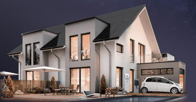
Above: BC Module Appearance
Below: Traditional Module Appearance
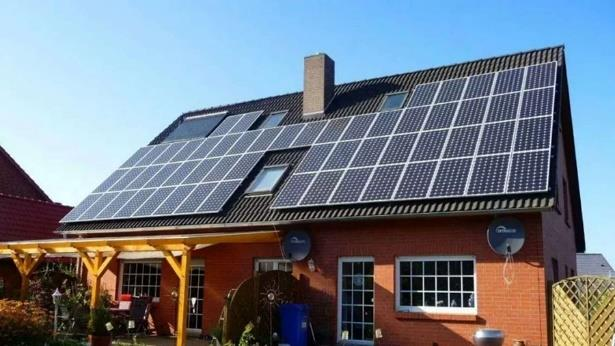
All-black module appearance aligns with architectural aesthetics, meeting high-end distributed market demand: The front-side grid-free design of BC cells gives them an all-black appearance, making them more visually appealing and easier to integrate into buildings compared to traditional modules with grid-like front-side metallization. This makes BC cells particularly suitable for high-end distributed applications such as villa rooftops, especially in markets like Europe. In overseas markets, BC modules command a premium of over $0.20/W compared to traditional PERC modules, reflecting their recognized aesthetic value.
Improved Bifaciality Facilitates BC Cell Entry into Utility-Scale Markets
Bifaciality gradually increases to 70%, potentially boosting rear-side power generation: By relocating front-side metallization to the rear side, BC cells increase rear-side shading, resulting in lower bifaciality (rear-side power generation efficiency/front-side power generation efficiency). For example, Aiko Solar's ABC modules initially had a bifaciality of only about 40%. Due to lower rear-side power generation gains, despite their higher front-side conversion efficiency, BC modules have limited penetration in utility-scale applications focused on LCOE. However, with technological optimization, Aiko Solar launched its "Stellar Series" modules with 70% bifaciality by the end of 2023, and LONGi released its Hi-Mo 9 product with similar bifaciality, matching the 65%-70% bifaciality of PERC technology.
Figure 3. Bifaciality Comparison of Different Cell Technologies
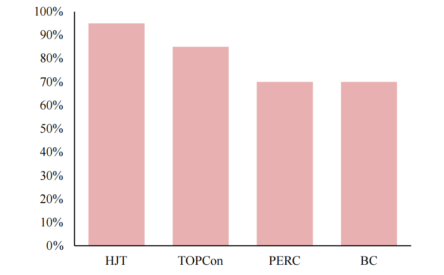
As shown above, ground reflectance typically ranges between 15%-30%, making bifaciality's impact on power generation relatively limited: Generally, the actual power generation of a photovoltaic cell equals the sum of front and rear-side power generation, i.e., "cell area × standard irradiance × front-side efficiency + cell area × (standard irradiance × ground reflectance) × (front-side efficiency × bifaciality)". In scenarios with lower ground reflectance, power generation is more sensitive to changes in front-side efficiency (i.e., conversion efficiency), while in scenarios with higher ground reflectance, power generation is more sensitive to changes in bifaciality. According to data from photovoltaic design software provider Candela, in typical utility-scale installation environments (e.g., deserts, grasslands, forests), ground reflectance generally ranges between 15%-30%. China's 2018 "Opinions on Benchmarking Photovoltaic Frontier Technologies" conservatively estimates rear-side reflectance at no more than 5%, indicating that bifaciality's impact on power generation is relatively limited. With 70% bifaciality, BC modules are expected to compensate for rear-side power generation losses through front-side efficiency gains.
How the Testing Industry Can Facilitate Further Maturation of BC Technology
Due to the current immaturity of BC cell processes, XBC cell yields remain relatively low. According to 2023 data, ABC (N-type) and HPBC (P-type) cells achieve yields of 93% and 95%, respectively, in the cell production stage, still significantly lower than the over 99% yield of TOPCon cells. A 1 percentage point increase in cell yield could reduce total cell production costs by approximately ¥0.004/W, highlighting the critical role of yield improvement in reducing BC technology costs.
As a leading enterprise in the photovoltaic cell testing industry, Yanzhi Testing has proposed corresponding solutions and related products to address these challenges.


 400-9662-958



 Location:


